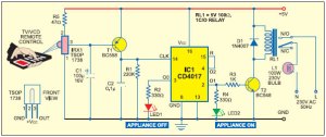
This is a very simple project for those students who wish to do some sort of mini projects in their first year college life.Connect this circuit to any of your home appliance to make the appliance turn on/off from a remote control.This circuit can be activated frm up to 10 metres
Make maximum use of the info. provided below.
The very first step you have to do is to buy all the components needed.Then,since you all are engineering students,u all will be knowing how to connect these components in the Bread board.Just connect these components in the bread board as specified in the circuit diagram.Obviously,everybody will get the output IF THE CONNECTIONS ARE PERFECT. But To do these much,you need not want to be an engineering student.Even a student studying in 8th or 9th can do this.so,What really does an engineering student should do is to LEARN from the project.Learn about each and every component used in the project.Go deeper and deeper into it.Dig out more and more information.
Nowadays,since we have more than enough number of engineering colleges near to us,the value of B-TECH has gone down.Wherever we go,we will find a college which provides this B-Tech or B.E course.so,nowadays,how companies recruit is not by just seeing our degree,they will look into the extra curricular activities,talents within us.So,to be somewhat different from other usual B-tech students,the only way is try these kind of projects.just take each project as timepass to do.Find fun in every success and failure of each project.you may get an output,or sometimes,you may not.It doesn’t matter.what matters is your attempt to do it.But,rather than just attempting,try to make it successful with the help of faculties,friends or any other sources.but i assure you that you will get the output for this project “REMOTE CONTROL:HOME APPLIANCES’ IF YOU USE THE BELOW MENTIONED NOTES
Sources for the information are many.I hope one among those sources will be this blog.MAKE USE OF IT EFFECTIVELY
MAJOR COMPONENTS USED IN THE PROJECT
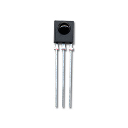
1)TSOP 1738 IR RECEIVER
This is a component which is used to receive IR rays transmitted from a remote control.
- In this component,Both receiving, Converting and Amplification occurs.
- It filters PCM frequency(will let you know what a PCM frequency is).
- It has both TTL and CMOS compatibility.(refer down to know what TTL and CMOS means)
a)Construction
Just hold the component like this In such a way that,the projection is facing you.
- The leftmost terminal – GROUND :- The terminal that you should connect to the ground.
- The rightmost terminal- OUTPUT :-The terminal which should be connected to the point where you need to get the amplified output from the receiver.
- The middle terminal- SOURCE :-The source of 5 V should be given to this terminal.
- Noise Immunity
- Low power consumption
- Low wastage as heat


5 responses to “Remote Control:Home Appliances”
athulat
July 8th, 2011 at 13:46
Good Work Keep Updating….
Chetan M.P
December 5th, 2011 at 23:01
Sir, the relay turns on, but doesn’t turns off… please assist me..
Goutham
December 10th, 2011 at 01:17
chetan,first of all,try changing the relay. defect relay can cause this problem.make sure that u have connected all pins correctly.my answer can be more specific if i can know which relay you are using?
Chetan M.P
December 10th, 2011 at 15:05
Sir, relay model is “KT-450” 5volt DC
Goutham
December 21st, 2011 at 22:57
chetan,just ensure that u didnt get confused on d common and normal pins…relay will work wit no complaints then..